


Magnetic Components
Enabling Global New Energy and Electronics Solutions
With the development of new energy vehicles towards high voltage and large-capacity batteries, boost inductors have been widely applied. In the design process of the magnetic core air gap of boost inductors, the problem of segmented setting of large air gaps often arises. Unreasonable air gap setting will lead to an increase in the AC loss of the coil, causing local overheating and affecting the service life of the product and the overall efficiency.
How large should a single air gap be, how to segment the air gaps, and where to place the air gaps for the best effect—these issues have always perplexed product development engineers. To address this problem, we used Ansys Maxwell simulation software to conduct multi-faceted analysis and calculations on high-power inductors in practical applications, studied and summarized the results, and combined with key points to note when using the simulation software to achieve efficient and accurate design optimization. The findings are now compiled into a report for sharing.
The following is the working principle diagram of PFC, where the boost inductor L is the research object of this article.
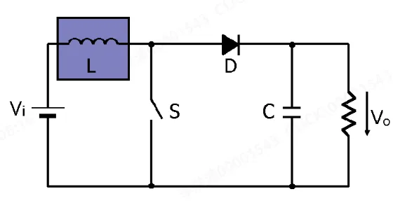
Its working principle is mainly based on electromagnetic induction and the energy storage characteristics of inductors. When the switch is turned on, the inductor stores energy and the current gradually increases; when the switch is turned off, the inductor generates a reverse high induced electromotive force, which is superimposed with the power supply voltage to achieve boosting. The voltage is then filtered and stored by a capacitor to provide a stable output voltage higher than the power supply for the load, thus completing the boosting process. Boost inductors play an important role in both pure electric vehicles and hybrid vehicles, serving as indispensable components in new energy vehicles.
This article has been published in the 11th China Joint Academic Annual Conference on Magnetic Components of Power Converters. It aims to explore the design and simulation optimization of the magnetic core air gap of boost inductors for electric vehicles, analyze the influence of the size and distribution of air gaps on inductor performance, and put forward reasonable design suggestions, so as to provide theoretical basis and practical guidance for designers of electric vehicle inductors.
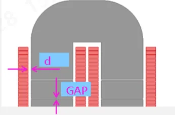
Relationship between GAP (Magnetic Core Air Gap) and d (Coil-to-Core Spacing)
In inductor design, GAP (air gap) and d (coil-to-core spacing) are two important parameters, and their relationship can be understood from the perspective of magnetic field and inductance calculation.
The air gap (GAP) in the magnetic core is mainly used to adjust the permeability and saturation characteristics of the magnetic core. The size of the air gap affects the ACR (AC resistance) and inductance of the magnetic core. The larger the air gap, the greater the ACR and the smaller the inductance.
The coil-to-core spacing d mainly affects the size of the area where the magnetic field lines cut the coil. The larger the cut area, the smaller the current passing through the coil, and the higher the temperature rise of the coil, 直至烧机、炸机 (until the machine burns out or explodes).
The air gap (GAP) is mainly used to increase the magnetic resistance inside the magnetic core, reducing the inductance. However, a large air gap (GAP) will make the cutting of magnetic field lines on the coil severe, increasing eddy current loss; a large coil-to-core spacing d will weaken the cutting effect of magnetic field lines on the coil, reducing eddy current loss.
In practical design, it is necessary to find a balance between the air gap and the coil-to-core spacing. An excessively large air gap (GAP) will lead to an increase in coil eddy current loss, affecting the power transfer efficiency of the product; an excessively large coil-to-core spacing d will increase the volume and cost, while an excessively small d will cause the coil to be cut by magnetic field lines.
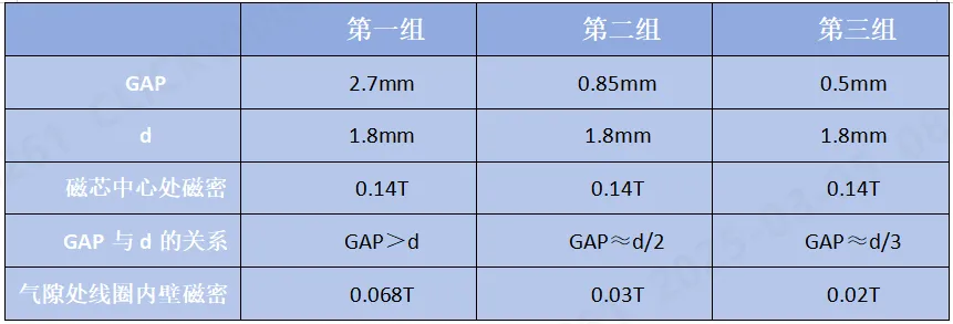
The following is a case of simulation results studying the size of GAP with the same coil-to-core spacing d=1.8mm:
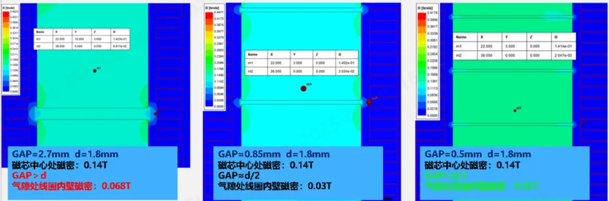
Influence of Different GAP Values on Coil Performance
To gain a deeper understanding of the influence of GAP on coil performance, further analysis shows that when GAP is equal to one-third of d, it is more ideal. At this time, the magnetic flux density at the leakage magnetic field of the inner wall of the coil at the air gap position is the lowest, which can be reduced to 0.02T.
【How to Segment the Magnetic Core Air Gap of Boost Inductors】
Segmenting the magnetic core air gap by dividing a single air gap into multiple small gaps aims to reduce magnetic flux leakage, minimize eddy current effects, improve thermal stability, precisely control inductance, reduce losses, and meet miniaturization and high-performance requirements.
The principles of air gap segmentation are: first, the size of a single GAP should not exceed 1/2 of the coil-to-core spacing d (generally, a single GAP ≈ d/3); second, the air gaps should be evenly distributed inside the coil, that is, the size and interval of the air gaps are consistent.
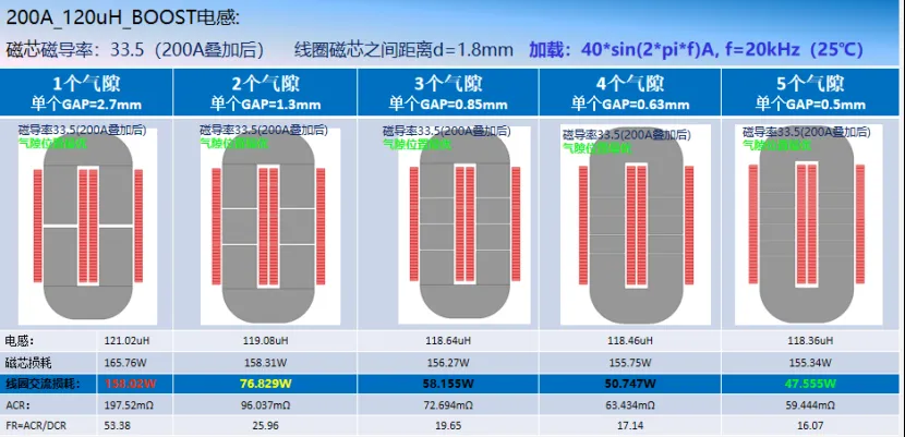
This article takes a 200A boost inductor as an example to analyze the influence of different air gap schemes on the loss of the inductor coil:
Kelic's practical application case: The current is 200A, the inductance is 120μH, and the peak-to-peak value of the ripple is 80A. In the design process, NPV material was selected as the iron core, and the final number of turns was determined to be 37 turns through calculation.
In the design, the focus was on studying the influence of air gap arrangement on losses. Specifically, the cases of one air gap, two air gaps, three air gaps, four air gaps, and five air gaps were analyzed, mainly focusing on core loss, coil loss, and ACR (alternating current resistance).
Through multiple simulations, it was found that as the number of air gaps increased, the loss gradually decreased. When the number of air gaps reached five, the system loss reached the minimum value. This result provides an important basis for the design optimization of boost inductors.
Subsequently, Kelic's team carried out a more in-depth segmentation study. When the air gaps were set to 6, 8, and 10 respectively, the AC loss did not significantly decrease. It can be concluded that setting 5 air gaps can meet the requirements in terms of production needs and cost control.
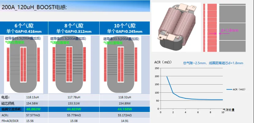
It is worth mentioning that for transformer and inductor design, ACR is a very important parameter. ACR refers to the resistance characteristics exhibited by an inductor in an AC circuit. Theoretically, the loss of an inductor is not only the DC loss caused by the DC resistance DCR, but more importantly, the loss of the ACR AC impedance, including the eddy current loss in the core and the losses caused by the skin effect and proximity effect, which together constitute the loss of the AC reactance ACR.
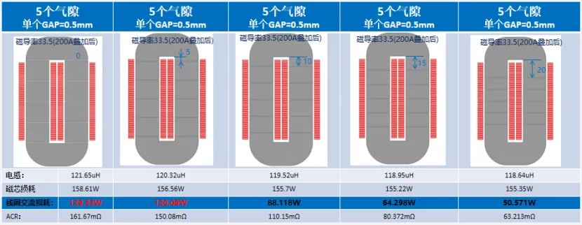
As mentioned earlier, 5 air gaps are an ideal configuration, but the specific position of the 5 air gaps requires further study.
The first diagram shows a U-shaped magnetic core, the second diagram adds a 5-mm 转折 (bend) to the U-shaped magnetic core; the third, fourth, and fifth magnetic cores add bends of 10 mm, 15 mm, and 20 mm respectively.
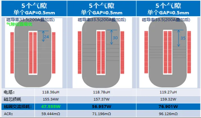
After repeated exploration, it was found that when the U-shaped bend size was 24 mm, the loss reached the optimal state. Based on this, the relevant data was summarized to sort out the relationship between the number of air gap segments, the optimal air gap size, and the ACR value.
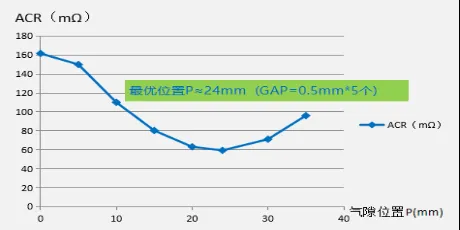
The reasonable and uniform distribution of the air gap position is crucial. Unreasonable air gap positions or uneven distribution will lead to increased coil loss. The following are the simulation results corresponding to the same air gap size and number but different positions.
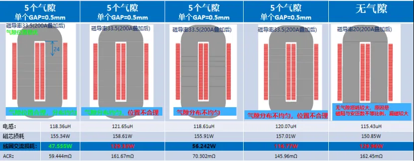
The research results show that when the inward extension is 24 mm and the placement position is uniform (see the following figure), the effect is the best. At the same time, the placement method has a significant impact on the results. As shown in the figure, when the air gap position is 24 mm, that is, GAP is 0.5 mm * 5, the ACR is the smallest.
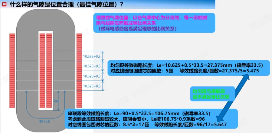
The ideal air gap position is to take the center of each air gap as the segmentation line, and the magnetic resistance of each segment is proportional to the ampere-turns of the coil. Toroidal inductors most easily satisfy this ideal proportional relationship.
The uniform segment and the series segment basically satisfy the equal ratio relationship, which has important reference significance for determining the optimal air gap position.
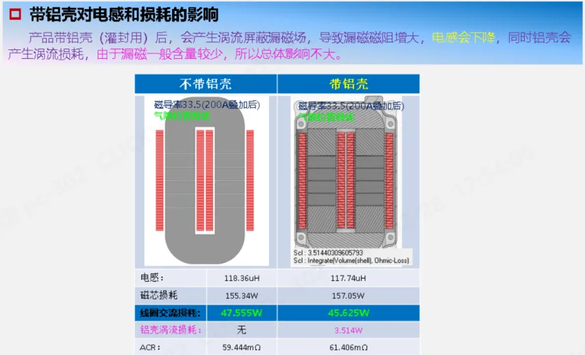
After potting the coil and installing the shell, through simulation analysis, we observed that the loss of the coil decreased. However, the shell itself generated an additional loss of 3.5 watts.
In other words, when the product is equipped with an aluminum shell (for potting), it will generate eddy current shielding of the leakage magnetic field, resulting in an increase in the leakage magnetic resistance and a decrease in inductance. At the same time, the aluminum shell will generate eddy current loss. Since the leakage magnetic field generally accounts for a small proportion, the overall impact is not significant.
Note: The above conclusions are only for metal powder core (core with magnetic permeability below 120) inductors, and other inductors can be used as references.
Through simulation research, we have gained a deeper understanding of the magnetic core air gap design of boost inductors for electric vehicles. Reasonable air gap design can not only optimize inductor performance and reduce losses but also improve the overall energy efficiency of electric vehicles. Future research can further explore the influence of different materials and structures on inductor performance and how to carry out more refined design combined with practical applications.


.pdf)

